 Assembly instructions
(Hyperspace Jump back to Part 1) Painting Assuming you have prepared the end cap, and made the angle cut in the upper PVC coupler, and drilled any holes you will need in the PVC, this is a good point to start the painting. To get good coverage and adhesion, I recommend dipping the parts completely in the paint. Only 3 parts in this design need paint: the PVC end cap, PVC ring (cut from the end cap), and the PVC coupler. For paint I used a 1/2-pint of glossy black, multi-surface latex. This size was large enough to dip all the parts I had, and also wasn’t very costly. Set up a “drip drying” area and a place to hang the parts. I used paper clips to create hangars, but any wire or string will do. Stir the paint thoroughly, and completely immerse each part you are painting for a few seconds. Lift the part out of the paint, and wait for a minute or two for most of the excess paint to run off, then hang the part up to continue dripping. To avoid having a big drip solidify at the lowest edge of the part, in about 15 to 20 minutes, gently dab the drip that will form with a paper towel or sponge. You might need to repeat this a few minutes later. After the first coat, let all the parts dry for 12–24 hours, and then give them a second coat. Don’t forget to stir the paint again. Wait at least 12 hours (24 is better) before trying to attach or work with the painted parts. (I was a little bit impatient, and have one small fingerprint on my upper PVC coupler to show for it.) Upper Tube Assembly This saber design uses two decorative caps, generally used to secure an overhead incandescent lamp shade. To connect them to the saber, you could just epoxy them on, but better results can be achieved by drilling 3/8" diameter holes in the chrome tube, and screwing a short piece of 3/8" threaded tube (also meant as part of an overhead light assembly—you will find both the caps and rod easily in a typical hardware store’s fan/lighting department) into the saber body, and then mounting the caps on it.
Nickel-plated caps, like these, make excellent “knobs.” Spencer Brown gave me an excellent alternate suggestion for the decorative buttons—these would be more similar to those used on the Graflex-tube sabers (see the FAQ and Links pages).
Because I didn’t have a drill large enough to do the job, my machinist friend Eric was kind enough to drill two semi-random holes in the upper body of the saber. (In fact, the position of one of the holes was decided by the fact that the piece slipped during milling, and the position for the slot had to be milled on the opposite side.) Where you put the knobs is entirely up to you. I definitely wanted one near the top of the saber, just at the base of the upper, angled PVC coupler, but wasn’t picky about the other. You’ll need a pair of pliers to screw in the threaded tube. The best thing to do is to screw in a longer piece of tube than you will actually use. The holes for this should be slightly smaller than the threads so the tube will “tap” threads into the sides of the hole—although if you have a really well equipped workshop you can measure the threads and thread the tube with a tap and die set. Be careful, as the chrome pipe isn’t very thick; you don’t want to strip the threads (although if you do, a dab of epoxy will allow you to recover somewhat gracefully). Once you’ve tapped the holes with the longer tube, cut two short pieces of it (3/8" to 1/2" in length) with a hack saw. If you have one available, putting a nut on one side of your cut will allow you to re-thread the portion of the rod that the hack saw will have mangled, but for this you can live without it. Using pliers, thread your two shorter pieces of the threaded tube partway into the 3/8" holes. You can then screw the nickel-plated caps on by hand. Slide the upper PVC coupler over the top of the saber, and line up its angle cut with the cut of the chrome tube. This should fit snugly, but if it doesn’t secure it with a little epoxy.
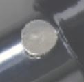
Old-style
(1970s) calculator display bubbles—I have Using a file, carefully rough the edge just around the milled slot, and epoxy the calculator display bubbles to the chrome tube.
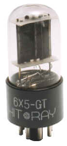
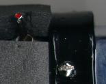
Carefully remove the plastic base and metal pins from the bottom of the electron tube, and get the glass base as clear as possible. As I was using a “vintage” tube, the plastic and original adhesive were so brittle this was very easy to do. Please be careful while doing this—especially if you are using a new tube. They are made of glass, and can shatter, although not very easily. Sadly, I disposed of the tube before getting down the number, although I’ve found some that are almost identical.
These
are a Hit Ray
6X5-GT (on the
left), and a Sovtek 6SN7 (on the right). Both are almost exactly like the tube I
used. (on the
left), and a Sovtek 6SN7 (on the right). Both are almost exactly like the tube I
used. You can get these from The Tube Store, or your local Radio Shack. Insert the electron tube which will form the “emitter array” into the top end of the saber. In my case, tightening the topmost decorative knob secures the tube (although mine has fallen out a couple of times so I probably need to change that aspect). You could do the same, or add a dab of epoxy, or even something less permanent light plastic-tack. Position the electron tube so that the base of it is just above the top of the calculator display bubbles, and secure it. Remember, the “emitter tube” is not part of the circuit, and does not serve any function other thank making the saber look good. It will not produce a “blade” or “beam.” That’s the last step, other than including the electronics for the light.
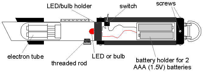
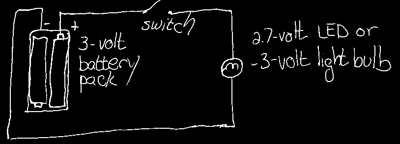
Cut-Away Diagram This drawing is also available for download in Windows Metafile (WMF) format, and CorelDRAW! 5.0 (CDR) format. Adding the LED, Batteries, and Switch The circuit used for the light is a very simple one. If you know how to solder, you’ll want to solder it together. If not, you can probably due with twisting the wires together. I used a super-bright, 2.7-volt LED, available in several colors from Radio Shack for about $4.00. You could easily use a 3-volt flashlight bulb instead, although an LED is a little more durable, and had the advantage of already being in the color I wanted. (Don’t let the words absolute maximum voltage on the back of the LED package scare you; a 2.7-volt LED will handle 3 volts without frying—what surprised me was that I didn’t need to limit the current with a resistor—it’s possible that this particular LED has one built in.)
I’ve
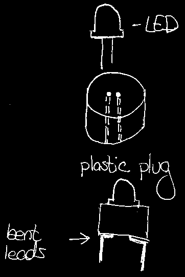
hidden my switch right between the top of Drill a small hole (I think about 3/16"—depending, of course, on the size of your switch) in the chrome tube where you will be mounting the switch. The best thing to do with the circuit is preassemble it outside the saber, with enough extra wire to make the components (especially the battery pack and switch) easy to move around. I took the plastic cylinder my friend Eric made to keep the chrome tube from distorting while milling, and cut about a 1/2" thick section off it. I drilled two small holes side by side about 1/4" apart in the center, and ran the leads of the LED through it, then bent them twice at 90° on the far side. This has the dual advantage of insulating the LED leads while forming an excellent platform for keeping the LED in position. Essentially, you want something that will hold the LED or light in the center of the saber—even a couple of circles cut out of corrugated cardboard will do.
LED mount. Attach the positive side of the 3-volt battery pack to one connector on the switch. Run a wire from the other connector on the switch to the positive lead (normally longer) on the LED. Run a wire from the negative lead on the LED to the negative side of the battery pack.
Circuit diagram. Test the circuit to be sure it works. If you are using an LED, remember that the “D” in LED stands for diode, and current will flow in only one direction; i.e., if you get the positive and negative leads reversed, the thing just won’t work. Use electrical tape (or any tape, really) to insulate any bare wire. The chrome tube is a conductor, and you don’t want to short out your circuit on the inside of the saber. Once you have the wiring done, you might want to wrap an elastic band or two around the batteries to keep them in the holder, then push the LED assembly into to saber. If you use a plug like I did, be sure to file down any rough edges you can find on the inside of the chrome tube, as the plug will get stuck if you don’t. (Even though I did, I still ended up having to gently hammer the plug into the final inch or so.) Push the switch into the saber, and try to get it to stick through the hole you’ve drilled for it. I accomplished this by using my file to move the switch around inside the saber and a strong light so I could see the lever part of the switch through the hole and grab it when I got it into position. Secure the switch by tightening its supplied ring nut with pliers. Slide the battery pack into the end of the saber. I threw in a spring to hold the battery pack against the side of the saber and keep it from getting loose. Put the D-ring assembly back on the end cap, and secure the end cap by putting in its four screws. That’s It!
My finished light saber. |